


Tolerances & Surface Finish for Tungsten Carbide Components in Wood Processing
Learn how cutting-edge geometry, functional tolerances, surface finish and carbide grade affect the fit and performance of woodworking carbide components.

Tungsten carbide is widely used in OEM components exposed to severe abrasion, particle erosion, sliding wear, pressure, repeated mechanical loading, and other demanding service conditions.
However, tungsten carbide should not simply be treated as a harder substitute for steel. Its high hardness, high elastic modulus, high compressive strength, and comparatively limited tolerance to tensile stress mean that material grade, geometry, tolerances, surface finish, support conditions, and assembly design must be considered together.
Successful OEM carbide components therefore begin with application-specific design rather than material selection alone.
This guide provides practical engineering considerations for OEMs designing custom tungsten carbide components for high-wear and severe-service industrial applications.
Tungsten carbide should be considered when component performance is limited primarily by wear, erosion, dimensional loss, or repeated maintenance rather than by structural loading alone.
Typical reasons for considering tungsten carbide include:
Tungsten carbide may also be used in applications involving impact, pressure, vibration, or elevated temperature, but these conditions require careful grade and component design.
It should not automatically be selected simply because an application is “severe.”
The dominant wear mechanism and mechanical loading must first be identified.
Cemented tungsten carbide combines hard tungsten carbide grains with a metallic binder, commonly cobalt or, for certain applications, alternative binder systems.
Its design behavior differs significantly from that of conventional steels.
Important properties include:
Because tungsten carbide performs particularly well under compression but is more sensitive to tensile stress, bending, and stress concentration, the component should be designed to minimize localized tensile loading whenever practical.
The appropriate balance between hardness and toughness must also be selected according to the actual wear mechanism.
Component geometry has a major influence on carbide reliability.
A carbide grade that performs well in one geometry may fail prematurely in another because of differences in stress distribution, section thickness, support, or assembly conditions.
Sharp internal corners create stress concentrations and should generally be avoided where practical.
Use appropriate radii or transitions between sections to distribute stress more gradually.
Edges exposed to mechanical loading, assembly forces, or impact should be reviewed carefully.
A radius that is too small may increase the risk of local cracking, while excessive radiusing may affect fit, sealing, or functional geometry.
The radius should therefore be selected according to the component function and load path.
Sudden changes in wall thickness can create localized stress concentrations.
Where possible, use smooth transitions between thick and thin sections.
Long unsupported carbide sections can experience bending or tensile stress.
Components should be designed so that carbide is appropriately supported by surrounding structures where required.
This is particularly important for:
Where possible, design the component so that primary loads are transferred through compression rather than bending or tension.
However, “design for compression” should not be interpreted as a universal rule. Actual contact conditions, assembly stresses, pressure loading, thermal effects, and system deformation must also be considered.
Wall thickness should be selected according to the wear allowance, mechanical loading, assembly method, and manufacturing requirements.
Very thin carbide walls can be more sensitive to:
Excessively thick carbide sections can increase:
The optimum section is therefore not necessarily the thickest possible carbide section.
For many OEM designs, localized carbide protection on the actual wear zone can provide a better balance of performance and cost than a fully carbide component.
Tungsten carbide components can be precision-ground to tight dimensional tolerances, but tolerance requirements should reflect component function rather than being applied uniformly.
Important considerations include:
Tight tolerances generally increase grinding and inspection requirements.
Therefore:
Early tolerance review can significantly improve manufacturability and cost control.
Interference assemblies are commonly used for carbide sleeves, rings, bushings, seats, and inserts mounted in steel housings.
However, interference must be carefully controlled.
Too little interference may result in:
Too much interference may generate excessive hoop stress in the carbide and increase the risk of cracking.
The correct interference depends on:
Generic interference percentages should therefore be avoided unless they have been validated for the specific component system.
Surface finish should be specified according to component function.
A controlled surface finish can reduce friction, limit localized contact stresses, and support dimensional consistency.
Valve seats, sealing rings, and other sealing interfaces may require fine grinding, lapping, or polishing depending on sealing requirements.
For nozzles, orifices, valve trim, and other flow-path parts, surface finish can influence flow behavior and localized wear, but erosion resistance should not be attributed to surface finish alone.
Particle characteristics, velocity, impact angle, geometry, and carbide grade usually have a much greater influence.
Surfaces used for brazing, bonding, or mechanical joining may require controlled preparation that differs from the preparation used for sealing or sliding surfaces.
The required finish should therefore be defined according to the joining process rather than assuming that a rougher surface is always preferable.
The assembly method must be selected as part of the component design—not after the carbide geometry has already been finalized.
Common OEM approaches include:
Mechanical retention can provide reliable support without directly joining the carbide to another material.
Care should be taken to avoid point loading, edge loading, and uneven clamping forces.
Brazing can be effective for certain carbide-to-metal assemblies, but joint design must consider:
Poor brazing design can introduce residual tensile stress into the carbide.
Steel generally expands more than tungsten carbide when temperature changes.
This difference can significantly affect interference fits and joined assemblies.
Thermal expansion should therefore be evaluated during both:
This is especially important where components experience elevated temperature or repeated thermal cycling.
OEM carbide design should begin with the dominant wear mechanism.
Evaluate:
Increasing carbide thickness may help in some applications, but simply maximizing carbide thickness is not always the most efficient design.
Evaluate:
Geometry should be designed to reduce severe localized particle impact where practical.
Evaluate:
Do not rely only on thicker carbide to resist impact.
Evaluate:
Binder selection can become as important as hardness in aggressive environments.
Evaluate:
Tungsten carbide should not be assumed to have a universal “high-temperature capability” without considering the complete component and assembly.
For many OEM applications, the best solution is not an all-carbide component.
A hybrid design can use:
Steel → structural support, toughness, mounting, and load distribution
Tungsten carbide → localized wear, erosion, sealing, or dimensional protection
Common examples include:
This approach can reduce carbide volume while placing the material where it provides the greatest engineering value.
OEM designers should consider the complete carbide manufacturing route before finalizing component geometry.
Typical processes may include:
Certain geometric features can significantly increase manufacturing difficulty or cost.
Examples include:
Early design review can often simplify the component without affecting its function.
For custom tungsten carbide components, drawings alone may not provide enough information to select the optimum material and manufacturing approach.
Where possible, OEMs should provide:
This information allows material, geometry, manufacturing, and assembly requirements to be reviewed as one engineering system.
For new or high-risk applications, prototype validation can reduce risk before full-scale production.
Depending on the component, validation may include:
Field results should be evaluated by looking at both wear rate and failure mode.
For example, changing to a harder carbide grade may reduce wear but introduce chipping. Increasing toughness may reduce cracking but increase material loss.
The objective is not simply to maximize hardness or wear life. It is to find the most reliable balance for the complete application.
Successful OEM carbide components require coordination among material selection, geometry, tolerances, surface finish, manufacturing, assembly, and actual operating conditions.
EnduraCarbide works with OEM engineers and technical teams to review custom tungsten carbide components based on drawings and application requirements.
Technical review can include:
Submit your drawings, specifications, current material, operating conditions, and known wear or failure problems for technical review.
Response within 24 hours • NDA available • Technical review included
The correct interference is a system-design parameter, not a universal percentage.
Cemented tungsten carbide and steel are frequently combined in severe-service components because the two materials provide complementary engineering properties.
Cemented tungsten carbide provides high hardness, wear resistance, compressive strength, and resistance to dimensional loss. Steel provides toughness, structural support, machinability, and the ability to incorporate mounting features such as threads, flanges, shoulders, and other connections.
The interface between these materials, however, requires careful engineering.
An interference fit that is too loose may allow movement, fretting, or loss of retention. Excessive interference can introduce damaging stresses into the carbide or permanently deform the steel housing. Thermal expansion, component geometry, wall thickness, surface condition, assembly method, and operating loads can further change the behavior of the joint.
This article explains the principal considerations for designing carbide-to-steel assemblies using press fits, shrink fits, and mechanical retention. The objective is not to provide a universal interference value, but to show which variables should be evaluated when developing and validating an assembly.
Cemented tungsten carbide combines hard WC grains with a metallic binder phase. Depending on the grade and application, this material system can provide excellent resistance to abrasion, particle erosion, dimensional wear, and high compressive loading.
However, carbide components must also be designed with their lower tolerance for tensile stress, bending loads, stress concentrations, and certain impact conditions in mind.
Steel provides a useful structural complement because it can:
This leads to a common design strategy:
Use carbide at the wear-critical interface and steel where structural support and attachment are required.
Examples include carbide inserts, sleeves, bushings, valve components, nozzles, wear elements, and other wear-critical parts supported by steel housings, holders, or bodies.
The appropriate configuration depends on component geometry, wear location, mechanical loading, operating environment, manufacturing requirements, maintenance strategy, and lifecycle considerations.
There is no universal component size or geometry at which a designer should automatically change from solid carbide to a carbide-to-steel construction.
A solid-carbide component may be appropriate when:
A carbide-to-steel assembly may be preferable when:
The decision should therefore be based on the complete component system rather than on a fixed dimensional rule.
Press fitting and shrink fitting are two methods commonly used to create an interference fit between a carbide component and a metallic housing.
In a press-fit assembly, the components are assembled mechanically, typically at or near the same temperature.
The method can be suitable when:
Because relative sliding occurs during assembly, friction, surface condition, alignment, edge geometry, and assembly force can influence the risk of scoring, seizure, edge damage, or localized stress.
In a shrink-fit assembly, a temperature difference temporarily creates assembly clearance. The steel housing may be heated, the carbide component may be cooled where appropriate, or a controlled combination may be used.
After temperatures equalize, the dimensional interference produces the intended contact pressure and retention.
Shrink fitting can reduce the sliding force required during assembly, but it introduces additional considerations involving:
Neither method is universally superior. Selection should depend on component geometry, materials, interference requirements, assembly capability, service temperature, required retention, and risk of damaging the carbide.
Interference is the dimensional difference between the mating carbide and steel surfaces before assembly at a defined reference condition.
The required interference should not be selected from a universal percentage or dimensional rule.
It depends on interacting factors including:
The design must provide sufficient retention without creating unacceptable stresses in the carbide or permanent deformation in the steel.
For critical assemblies, analytical calculations, appropriate numerical analysis, controlled assembly trials, and application validation can all form part of the design process.
Interference creates contact pressure at the carbide-to-steel interface.
The resulting stress state is affected by component geometry and cannot be described simply as “compression in the carbide and tension in the steel.”
Although interference can place significant regions of the carbide under beneficial compressive stress, local tensile, shear, or bending stresses may still develop depending on:
This is especially important for carbide rings, sleeves, and bushings, where excessive interference or unfavorable geometry can contribute to cracking.
The complete stress field should therefore be considered rather than relying only on nominal interference.
Carbide wall thickness strongly influences the stiffness and stress response of sleeves, rings, and bushings.
A relatively thin carbide section may be more sensitive to:
However, there is no universal minimum wall thickness expressed as a percentage of component diameter.
Appropriate wall thickness depends on:
Abrupt changes in section should also be evaluated carefully because they can introduce local stress concentrations.
The steel housing is part of the interference-fit system and should not be treated as an infinitely rigid boundary.
Under interface pressure, the housing can expand elastically. The amount of deformation depends on:
If the housing undergoes excessive elastic deformation, the available retention may decrease. If it plastically deforms, the intended fit can be permanently altered.
The housing should therefore be designed together with the carbide component rather than after the carbide dimensions have already been fixed.
Surface condition is an important functional variable in interference-fit assemblies.
It can affect:
Carbide mating surfaces are commonly precision ground where dimensional control and surface integrity are important.
Steel mating surfaces should likewise be manufactured with suitable dimensional accuracy and surface condition for the selected assembly method.
Rather than applying one universal surface-roughness specification, the required finish should be determined from the component size, tolerance, assembly process, retention requirement, and service conditions.
Lead-in geometry and edge treatment should also be designed to support alignment and reduce the possibility of carbide edge loading during assembly.
Cemented tungsten carbide and steel have different coefficients of thermal expansion.
In many carbide-to-steel combinations, steel expands more with increasing temperature than cemented tungsten carbide. As a result, operating temperature can change interface pressure and effective retention.
Thermal behavior should therefore be evaluated across the expected service-temperature range rather than only at room temperature.
Important factors include:
Thermal cycling can also contribute to interface movement, fretting, changes in contact pressure, or fatigue-related damage in some applications.
The design should therefore verify adequate retention and acceptable stresses across the relevant thermal operating range.
An interference fit does not always need to carry every axial or torsional load through interface friction alone.
Depending on the application, positive mechanical retention may provide a more robust load path.
Possible retention features include:
| Retention Method | Potential Function | Engineering Considerations |
|---|---|---|
| Steel housing shoulder | Axial location and load transfer | Avoid concentrated carbide edge loading; use appropriate transition geometry. |
| Stepped carbide geometry | Axial positioning or retention | Consider carbide manufacturability and stress concentration. |
| Threaded retainer or lock nut | Controlled axial retention | Avoid excessive preload or bending of the carbide. |
| Mechanical clamping | Replaceable retention | Distribute clamping force and prevent localized loading. |
| Positive drive feature in supporting structure | Torque transmission | Keep severe stress concentrations away from vulnerable carbide regions. |
| Retaining compound or engineered bonding system | Supplemental retention or interface control | Verify compatibility with temperature, chemistry, loading, and maintenance requirements. |
The appropriate method depends on the load path and service conditions.
Where high axial loads, torque, vibration, impact, or thermal cycling are present, the designer should evaluate whether positive retention can reduce dependence on uncertain interface friction.
Cemented tungsten carbide performs particularly well when loads are appropriately distributed and predominantly compressive.
Localized edge contact, point loading, bending, or severe stress concentration can significantly increase the risk of chipping or fracture.
Potential problems include:
Design practices should therefore aim to:
Failure analysis can provide valuable information about whether a problem originates from material selection, interference, geometry, support, assembly, or operating conditions.
Possible contributors include:
Possible contributors include:
Possible contributors include:
Possible contributors include:
Failure patterns should be treated as diagnostic evidence rather than as proof of a single root cause.
A systematic approach helps reduce the risk of applying generic fit rules to very different carbide assemblies.
Determine what the carbide element must resist:
Identify:
Determine which loads should be carried by the carbide, the steel, the interface, and any mechanical retention features.
Consider:
Evaluate the carbide grade according to wear resistance, toughness, binder system, corrosion requirements, geometry, and manufacturing considerations.
Select the steel according to strength, toughness, stiffness, corrosion requirements, thermal behavior, machinability, and assembly requirements.
Evaluate:
Check the assembly across relevant manufacturing and operating conditions rather than only at nominal room temperature.
For critical components, analytical calculations or numerical analysis may be appropriate.
Specify:
Prototype or field validation should confirm:
Field results can then be used to refine the interference, geometry, material selection, or retention strategy.
For custom OEM components, useful engineering information includes:
The more accurately the operating and assembly conditions are defined, the more effectively the carbide component and interface can be evaluated.
Successful carbide-to-steel assemblies depend on more than selecting an interference percentage.
Carbide grade, steel properties, wall thickness, housing stiffness, interface geometry, dimensional tolerances, surface condition, differential thermal expansion, mechanical loads, assembly method, and retention features all interact to determine performance.
The most reliable approach is therefore to treat the carbide, steel housing, interface, and retention system as a single engineered assembly.
For OEM applications, interference should be calculated and validated for the actual component geometry and operating conditions—not selected from a universal rule of thumb.
Specify tolerances according to function—not simply the tightest tolerance that can be manufactured.
Precision tungsten carbide components often require tighter dimensional and surface control than conventional wear parts, but tighter is not automatically better.
Every additional tolerance, geometric requirement, or surface-finish specification can affect manufacturing method, grinding time, inspection effort, lead time, and cost. At the same time, insufficient control of a functional surface can compromise fit, sealing, alignment, load distribution, or service performance.
The objective of good OEM design is therefore not to specify the tightest practical tolerance on every dimension. It is to identify which features are functionally critical and apply the appropriate level of precision to those features.
This article explains how sintering, precision grinding, EDM, lapping, geometric tolerances, surface condition, and functional requirements should be considered when specifying cemented tungsten carbide components.
Cemented tungsten carbide is manufactured differently from conventional wrought or machined steel.
A typical carbide manufacturing route may include:
During sintering, the pressed carbide body densifies and undergoes dimensional shrinkage. The expected shrinkage and resulting dimensional behavior depend on the grade, powder characteristics, forming process, geometry, sintering control, and manufacturing consistency.
For this reason, precision carbide components are commonly designed around two dimensional conditions:
the sintered preform and the finished component.
Surfaces that do not require high precision may remain in the as-sintered condition, while critical surfaces can be left with suitable finishing allowance and brought to final dimension by grinding, EDM, lapping, polishing, or another controlled finishing process.
This distinction is fundamental to cost-effective carbide design.
Not every surface of a tungsten carbide component needs precision finishing.
An as-sintered surface may be appropriate when it:
Examples may include certain non-mating exterior surfaces or wear surfaces where precise dimensional control is not necessary.
Finishing is normally considered when a surface controls:
The drawing should therefore clearly distinguish between surfaces that may remain as-sintered and surfaces that require final machining or finishing.
A precision carbide component is often manufactured from a sintered preform that contains additional material on surfaces requiring subsequent finishing.
This additional material is commonly referred to as grind allowance or finishing allowance.
The appropriate allowance depends on factors such as:
Too little allowance can make it difficult to remove dimensional variation or surface defects.
Excessive allowance can increase grinding time, material removal, wheel wear, thermal exposure, manufacturing cost, and lead time.
Preform design should therefore be coordinated with the intended finishing process rather than treated as an independent manufacturing step.
Diamond grinding is widely used to finish cemented tungsten carbide because of the material's high hardness.
Precision grinding may be required for:
However, grinding should be specified because the component function requires it—not simply because a ground surface appears more precise.
Where the application can accept an as-sintered surface, unnecessary grinding adds manufacturing cost without necessarily improving performance.
One of the most important steps in OEM carbide design is distinguishing critical dimensions from non-critical dimensions.
A dimension may be critical when it affects:
These dimensions may justify tighter dimensional or geometric control.
A dimension may be non-critical when it:
Applying unnecessarily tight tolerances to non-functional surfaces increases manufacturing effort and inspection requirements without providing an engineering benefit.
The tolerance should reflect the function of the feature.
Outside and inside diameters frequently control the function of carbide sleeves, bushings, rings, valve components, nozzles, inserts, and carbide-to-steel assemblies.
The appropriate OD or ID tolerance depends on:
For interference-fit components in particular, the carbide dimension cannot be specified independently from the mating steel component.
The complete tolerance stack should be evaluated so that all acceptable carbide-and-steel combinations remain within the intended fit range across the specified manufacturing tolerances.
This is more useful than automatically assigning the same tight tolerance to every carbide diameter.
A common drawing error is to specify a carbide diameter with a tight tolerance without fully defining the mating component or the required fit.
A dimensional tolerance defines the permissible size variation of one feature.
A fit depends on the relationship between two mating features.
For example, an interference-fit design must consider:
Therefore, tighter carbide tolerance alone does not guarantee a better or more reliable fit.
The complete mating system must be specified.
Dimensional accuracy alone does not ensure functional geometry.
Depending on the application, geometric controls may be needed for:
The required geometric control should be selected from the component's actual function.
For example, a rotating carbide sleeve may require a controlled relationship between its bore and outside diameter, while a sealing ring may place greater emphasis on flatness and relationship between sealing and locating surfaces.
The relevant datum structure should also reflect how the component is assembled and used.
Rotating and reciprocating carbide components can be sensitive to geometric misalignment.
Excessive runout or misalignment may contribute to:
When a carbide OD, ID, sealing feature, or other functional surface must operate relative to a common axis, the drawing should identify the appropriate datum and geometric requirement.
Manufacturing strategy may also matter. Where practical, related precision surfaces can be finished using consistent locating references to reduce accumulated setup error.
The required runout or related geometric tolerance should be determined from operating speed, mating geometry, clearance, load, sealing requirements, and the complete assembly design.
Flatness and parallelism are important for many carbide components, including:
The required control depends on how the surface functions.
A sealing interface may require substantially greater control than a non-mating end face. Likewise, parallelism may be important when two opposing surfaces establish component position, clearance, load distribution, or alignment.
These requirements should therefore be derived from the assembly function rather than from a universal carbide specification.
Surface finish influences more than appearance.
Depending on the application, it can affect:
The appropriate surface condition depends on the intended function and mating system.
A sealing face, sliding surface, interference-fit diameter, abrasive wear surface, and non-contact exterior surface do not necessarily require the same finish.
For this reason, surface finish should be specified selectively on the drawing and tied to functional surfaces.
Carbide is widely used in sealing and flow-control applications because of its hardness, wear resistance, dimensional stability, and ability to achieve high-quality surface finishes.
However, sealing performance is influenced by more than surface roughness alone.
Important factors can include:
For precision sealing components, requirements should therefore be established for the complete sealing system.
A very fine finish cannot compensate for incorrect geometry, insufficient contact, distortion, or unsuitable operating conditions.
Carbide surfaces used for sliding or guiding must balance wear resistance with the tribological requirements of the mating system.
Relevant factors include:
An extremely smooth surface is not automatically optimal for every sliding application.
Depending on the tribological system, surface texture may influence lubricant retention, friction, running-in behavior, and wear.
The appropriate finish should therefore be selected based on the actual contact conditions.
Surfaces used in carbide-to-steel interference fits require coordinated dimensional and surface control.
Relevant factors include:
Surface irregularities can affect effective contact and assembly behavior, while unfavorable machining marks or localized defects can contribute to stress concentration.
However, there is no single surface-finish value that is universally correct for every carbide interference fit.
The surface requirement should be developed together with the interference design and assembly process.
Lapping and polishing can be used when the application requires very high levels of surface quality, form control, or contact performance.
Typical applications may include:
These processes can provide surface quality beyond conventional grinding, but they also add manufacturing steps, inspection requirements, cost, and lead time.
They should therefore be specified when the functional benefit justifies the additional processing.
Electrical discharge machining can be useful for carbide features that are difficult or impractical to produce by conventional grinding.
Examples include:
EDM can alter the near-surface condition of cemented carbide. The extent and significance of the affected layer depend on the EDM process, energy settings, carbide grade, geometry, and subsequent service requirements.
For fatigue-sensitive, sealing, highly stressed, or otherwise critical surfaces, the required post-EDM condition should be evaluated.
Depending on the application, additional finishing or surface treatment may be appropriate.
It is therefore better to specify the required final surface condition than to assume that every EDM surface must receive the same post-processing operation.
Grinding cemented tungsten carbide requires controlled processing.
Important factors can include:
Poorly controlled grinding can introduce:
The objective is therefore not simply to reach the required dimension, but to achieve the required dimension while maintaining acceptable surface integrity.
For severe-service components, surface condition should be considered part of manufacturing quality rather than only a cosmetic requirement.
Tighter tolerances generally increase manufacturing effort because they may require:
The relationship is not a fixed cost multiplier because it depends on component geometry, size, carbide grade, quantity, process route, equipment, and required inspection.
However, the general principle is clear:
Precision should be purchased where it creates functional value.
Applying high-precision requirements to every feature can increase cost and lead time without improving component performance.
A well-defined OEM drawing should provide enough information for the carbide manufacturer to understand both the geometry and the engineering intent.
Depending on the component, useful information includes:
Specify:
Avoid relying only on an internal or regional grade designation unless the required material characteristics are also understood.
Clearly identify:
Where functionally necessary, specify:
Identify:
Specify:
For critical features, define:
The drawing should communicate what matters to component function rather than simply impose maximum precision everywhere.
In addition to the drawing itself, application information can significantly improve engineering review.
Useful information may include:
This information helps distinguish dimensions that are genuinely function-critical from those that can use more economical manufacturing tolerances.
A systematic approach can help avoid both under-specification and over-specification.
Determine which surfaces:
Review the tolerances and geometry of the mating components rather than specifying the carbide component in isolation.
Determine the allowable:
Decide which surfaces may remain:
Assign tighter tolerances and surface requirements only where needed to meet the functional requirements.
Confirm that the combination of:
can be produced reliably.
For high-precision or severe-service components, first-article inspection, assembly trials, functional testing, or field validation may be appropriate.
Specify tolerances according to function—not simply the tightest tolerance that can be manufactured.
A well-designed carbide drawing:
The objective is not to manufacture the most dimensionally precise carbide component possible.
The objective is to manufacture a component with the precision necessary to perform its intended function reliably and consistently.
Tolerances and surface finish are fundamental parts of precision tungsten carbide component design.
Because cemented carbide is formed, sintered, and then selectively finished, OEM designers should consider manufacturing route, component geometry, functional surfaces, mating components, surface integrity, and inspection requirements when defining dimensional specifications.
Critical sealing, locating, sliding, rotating, and interference-fit surfaces may require close dimensional and geometric control. Other surfaces may not benefit from the same level of precision.
The best carbide drawing is therefore not the drawing with the greatest number of tight tolerances.
It is the drawing that applies the right tolerance and surface requirement to the right feature for the right engineering reason.
A carbide fracture problem is not necessarily a carbide-grade problem. Geometry, support, assembly, and load distribution may be equally important.
When a cemented tungsten carbide component fractures in service, one of the first questions is often whether a tougher carbide grade is required.
Grade selection is important, but fracture cannot be evaluated from material properties alone.
A carbide component may have an appropriate hardness–toughness balance for the application and still fail because of:
Conversely, changing to a tougher grade may improve fracture resistance in some applications, but it will not necessarily correct a structural design problem.
Effective carbide design therefore requires the material, component geometry, support structure, assembly method, and operating loads to be considered as one system.
This article explains the principal OEM design factors that influence stress concentration and fracture risk in cemented tungsten carbide components.
Cemented tungsten carbide is a composite material consisting primarily of hard WC grains bonded by a metallic binder.
The WC phase provides high hardness and resistance to abrasive and erosive wear, while the binder phase contributes cohesion and toughness.
Compared with many engineering steels, cemented tungsten carbide generally combines:
These differences have an important design consequence:
A design geometry that performs reliably in steel cannot automatically be transferred to cemented tungsten carbide without reviewing the stress state and load path.
Carbide components should therefore be designed with particular attention to:
Cemented tungsten carbide performs particularly well under appropriately distributed compressive loading.
However, real components rarely experience a purely compressive or purely tensile stress state.
Local tensile, shear, bending, and contact stresses can develop because of:
For this reason, “design carbide for compression” is a useful principle, but it should not be interpreted as meaning that compression automatically makes a design safe.
The objective is to:
The complete stress field should be considered for critical components.
Cemented tungsten carbide is relatively stiff and has limited ability to redistribute localized stresses through plastic deformation.
In a ductile metallic component, local yielding may sometimes reduce the severity of a stress concentration.
Cemented carbide provides far less accommodation of this type.
As a result, local geometry and contact conditions can have a strong effect on fracture behavior.
Examples include:
The practical design principle is therefore:
Do not rely on the carbide to compensate for poor alignment, uneven support, or concentrated loading.
These conditions should be controlled by the geometry and the surrounding assembly.
Internal corners, grooves, shoulders, slots, and other re-entrant features can create local stress concentrations.
The severity depends on:
Where function permits, abrupt internal transitions should be replaced with smoother geometry.
Possible approaches include:
There is no universal minimum corner radius suitable for every carbide component.
The appropriate radius should be selected according to the component size, load path, available space, manufacturing method, and required function.
External carbide edges are vulnerable to localized damage during:
An unnecessarily sharp edge may increase the likelihood of:
Where the function does not require a sharp edge, an appropriate:
can improve robustness.
However, edge geometry should remain application-specific.
For example, a cutting edge, metering edge, sealing edge, locating feature, and protected non-functional edge may require very different treatment.
A universal edge-break dimension should therefore not be applied to all carbide components.
Changes in component cross-section alter the way stresses flow through the part.
Abrupt transitions may increase localized stresses, particularly under:
Potential improvements include:
The optimum transition geometry depends on the diameter or section ratio, loading direction, component stiffness, material grade, and surrounding assembly.
Fixed radius-to-diameter ratios should therefore be treated cautiously rather than as universal carbide rules.
Thin carbide sections can be more sensitive to:
However, there is no universal minimum wall thickness expressed as a percentage of component diameter.
The required section thickness depends on:
For thin sleeves, rings, bushings, and other slender geometries, the designer should evaluate the complete structural system rather than applying a fixed wall-thickness rule.
Unsupported or poorly supported carbide can experience bending or concentrated loading even when the nominal external load appears moderate.
Examples include:
Good support design aims to:
“Fully supported” should not be interpreted as requiring every carbide surface to contact steel.
The appropriate support area depends on how the load enters and leaves the carbide component.
Bending deserves particular attention in carbide component design because it creates non-uniform stress through the component section.
Depending on the geometry and loading direction, one region can experience tensile stress while another is in compression.
Where possible, the load path should be designed so that the carbide primarily performs the wear-resistant function while a tougher supporting structure carries major structural bending loads.
Possible strategies include:
Where bending cannot be avoided, the carbide grade, geometry, section dimensions, surface condition, support, and expected load spectrum should all be considered together.
Localized contact is a frequent source of high stress in carbide components.
Possible causes include:
Design measures may include:
Any compliant layer, shim, gasket, coating, or intermediate material must itself be evaluated for temperature, chemistry, creep, wear, stiffness, and assembly conditions.
It should not be assumed that adding a “soft” layer is automatically beneficial.
Press fits and shrink fits can introduce substantial stresses into carbide components.
The resulting stress state depends on:
An interference fit may provide useful retention and can place some regions of the assembly under favorable compression, but it can also generate unfavorable local stresses.
The critical location cannot be assumed from a simple universal rule.
For precision or highly loaded assemblies, the design should evaluate:
If acceptable retention cannot be achieved without excessive carbide stress, mechanical retention or a different interface concept may be preferable.
Carbide and steel often perform best when their functions are deliberately separated:
carbide provides wear resistance at the critical interface, while steel provides structural support, attachment, and load management.
The steel support should therefore be designed as part of the carbide system.
Important considerations include:
The support should avoid introducing:
The steel housing does not necessarily need to be “stiffer than carbide.” What matters is that the supporting system provides adequate stiffness and contact stability for the actual load case.
A correctly designed carbide component can still be damaged by an unfavorable assembly process.
Assembly-related risks include:
Useful design considerations include:
No universal lead-in angle or assembly temperature should be applied to all components.
These should be determined by the specific geometry and assembly process.
Carbide components may experience stress changes as the assembly temperature changes.
Important factors include:
Thermal effects can alter:
Thermal cycling can also interact with mechanical loading, wear, corrosion, or interface movement.
The complete operating temperature range should therefore be considered during design rather than evaluating the component only at room temperature.
Impact, vibration, and repeated loading can increase fracture risk, particularly when combined with:
Improving robustness may involve:
There is no single microstructure that provides maximum impact resistance for every application.
The appropriate balance between hardness, toughness, wear resistance, binder system, and microstructure depends on the specific impact energy, loading mode, wear mechanism, geometry, and service environment.
Vibration may contribute to:
Potential corrective measures depend on the cause and may include:
Adhesives or retaining compounds may be useful in some assemblies, but their suitability depends on:
They should not be treated as a universal solution for carbide interface movement.
Before changing the carbide grade, it is important to determine how the component actually failed.
Possible characteristics include:
Potential contributing mechanisms may include:
Possible characteristics include:
Possible contributing causes include:
Visual appearance alone does not always establish the root cause.
Fracture surfaces, load history, service conditions, assembly condition, dimensional evidence, and material examination should be reviewed together where the failure is critical.
A longitudinal crack, chipped edge, fractured corner, or broken sleeve may suggest certain loading conditions, but no single fracture pattern should automatically be assigned one cause.
For example, cracking can result from combinations of:
Failure analysis should therefore ask:
This approach is more reliable than selecting a new grade based only on the final appearance of the broken component.
A grade change can be appropriate when the failure analysis indicates that the existing hardness–toughness balance is not suitable for the actual service conditions.
Examples may include applications involving:
A tougher grade may be achieved through changes in:
However, greater toughness may involve tradeoffs with properties such as:
For this reason, a tougher grade should be selected as part of the complete design review rather than as an automatic response to fracture.
If a carbide component fractures at a clear stress concentrator, simply changing the grade may leave the underlying cause unchanged.
Examples include:
| Observed problem | Design factors to review |
|---|---|
| Fracture near an internal corner | Radius, section transition, local load path, and surface condition |
| Cracking after assembly | Interference, mating tolerances, alignment, housing stiffness, and assembly process |
| Edge chipping | Edge geometry, point loading, support, handling, and contact alignment |
| Fracture near an unsupported section | Support length, overhang, bending, and load distribution |
| Repeated fracture at the same location | Geometry, local stress, assembly condition, and operating load history |
| Fracture after thermal cycling | Differential expansion, constraint, temperature gradients, and interface design |
The appropriate corrective action should follow the failure mechanism.
Sometimes this will be a geometry change.
Sometimes it will be a support or assembly change.
Sometimes it will be a grade change.
Often, the most reliable solution combines several of these.
A useful design-review sequence is:
Determine whether the problem is primarily:
Identify:
Examine:
Check:
Evaluate:
Include:
Only after the structural and service conditions are understood should the hardness–toughness balance, WC grain characteristics, binder system, and other grade variables be reconsidered.
For an OEM engineering review, useful information includes:
Failed samples can also be valuable when available because the crack origin, fracture path, wear pattern, and interface condition may provide important diagnostic information.
A carbide fracture problem is not necessarily a carbide-grade problem. Geometry, support, assembly, and load distribution may be equally important.
When a carbide component fractures:
Cemented tungsten carbide provides exceptional hardness and wear resistance, but reliable component performance depends on much more than material grade.
Geometry, wall thickness, section transitions, edge condition, support, assembly interference, housing stiffness, alignment, thermal behavior, impact, vibration, and load distribution can all influence local stresses and fracture risk.
For OEM designers, the most effective approach is therefore to treat the carbide component as part of the complete mechanical system.
When fracture occurs, the first question should not simply be:
“Do we need a tougher carbide grade?”
The more useful questions are:
Where did the crack begin? How was the load transferred? Was the carbide adequately supported? Did the geometry or assembly create a local stress concentration?
Once those questions are answered, grade selection can be evaluated together with geometry, support, assembly, and actual service conditions.
The goal is not merely to select a carbide that is harder or tougher.
It is to design a carbide component and supporting system in which material properties, geometry, load path, and manufacturing work together to provide reliable severe-service performance.
Dimensional accuracy, edge geometry and surface finish can strongly influence the cutting performance and service life of tungsten carbide components used in wood-processing tools. The appropriate specifications depend on the component design, carbide grade, machining method, tool assembly and operating conditions—not simply on achieving the tightest possible tolerance.
Wood-processing tools operate under demanding conditions involving repeated cutting contact, abrasive wood fibers, resins, adhesives and engineered materials such as MDF, particleboard, plywood and laminates.
Tungsten carbide is widely used for wear-critical cutting components because it combines high hardness, wear resistance and the ability to maintain precise cutting geometries. However, carbide grade alone does not determine performance. Dimensional accuracy, cutting-edge geometry, surface condition and consistency between components can all influence how effectively the carbide performs in service.
For custom carbide components, precision requirements should therefore be defined according to the actual application. A saw tip, planer knife, reversible insert and profile insert may require very different dimensional and surface specifications even when manufactured from similar carbide materials.
The geometry of a carbide cutting component determines how the cutting edge engages the workpiece, forms the chip and transfers mechanical loads into the tool body.
Important geometric features can include:
The relative importance of these features depends on the application.
Sawing, planing, profiling, grooving and trimming each create different contact conditions between the carbide edge and the workpiece. Solid wood also behaves differently from engineered panels or laminated materials.
As a result, carbide component geometry should be developed around the intended cutting operation rather than treated as a universal specification.
Wood is anisotropic: its cutting behavior changes with fiber direction. Cutting along the grain, across the grain or through composite wood-based materials can produce different cutting forces, chip formation and edge-loading conditions.
Engineered wood products introduce additional variables. Adhesives, mineral contaminants, coatings and abrasive surface layers can accelerate cutting-edge wear compared with many natural wood applications.
The geometry selected for a carbide component should therefore consider both the machining operation and the material being processed.
For precision cutting applications, small variations between carbide components can affect assembled-tool performance.
Important considerations may include:
This becomes particularly important when multiple carbide inserts or tips operate together in the same cutting assembly.
Tolerance requirements for cemented tungsten carbide components vary considerably according to component size, geometry, manufacturing route and final application.
A sintered carbide blank, for example, does not normally require the same dimensional condition as a precision-ground cutting insert.
Similarly, a carbide blank that will subsequently be brazed and ground, or mechanically retained may have different dimensional requirements from a finished insert whose geometry directly determines the cutting profile.
For this reason, specifying a universal tolerance for all woodworking carbide components can lead to either unnecessary manufacturing cost or inadequate precision.
A better approach is to identify which dimensions directly influence component function.
For a carbide saw tip, these may include the dimensions affecting seating, brazing and final cutting geometry.
For a reversible knife, thickness, length, locating features and edge geometry may be more important.
For a profile or moulder insert, the accuracy of the cutting profile can become the critical characteristic.
Engineering drawings should therefore distinguish between:
Critical dimensions — dimensions directly affecting cutting geometry, location, fit or assembly.
Functional dimensions — dimensions requiring controlled accuracy but allowing a broader tolerance.
Non-critical dimensions — features where tighter tolerances provide little or no practical performance benefit.
This approach concentrates manufacturing precision where it actually contributes to component performance.
Dimensional tolerances alone do not fully define a precision carbide component.
Depending on the design, additional geometric requirements can include:
For components installed in rotating tooling, the cumulative effect of individual component tolerances can also influence the assembled tool.
This is why component drawings should define not only nominal dimensions but also the geometric relationships that are functionally important.
Surface-finish requirements for tungsten carbide should be determined by the function of each surface.
A seating surface, brazing surface, locating feature and cutting edge do not necessarily require the same finish.
Precision grinding can provide controlled dimensions and smooth functional surfaces. Additional finishing or polishing may be appropriate where lower surface roughness contributes to cutting performance, reduced friction or easier material release.
However, specifying an exceptionally fine finish on every surface can add manufacturing cost without providing a corresponding performance benefit.
The objective should therefore be functionally appropriate surface quality, not simply the lowest achievable roughness value.
For woodworking applications, the condition of the cutting edge is particularly important.
Grinding defects, edge chipping or inconsistent edge preparation can affect:
A high-quality carbide component should therefore be evaluated not only by its overall dimensions but also by the condition and consistency of its functional edges.
Wood-processing applications can expose cutting components to resin, adhesives and other deposits.
Surface condition can influence how readily these materials adhere to the carbide component. Accumulated material may alter cutting conditions, increase friction or interfere with chip evacuation.
An appropriate finish on relevant surfaces may make deposits easier to remove. Actual buildup also depends on wood species, panel composition, cutting temperature, tool geometry and operating conditions.
Achievable cutting-edge quality is not determined by grinding alone.
The microstructure of cemented tungsten carbide—including WC grain characteristics, binder content and manufacturing consistency—also influences hardness, toughness, edge stability and wear behavior.
Fine-grained carbide grades are often considered where sharp, stable cutting edges and high wear resistance are important. However, simply selecting the finest grain or highest hardness is not always the correct solution.
Applications involving greater mechanical loading, interrupted cutting or edge-impact conditions may require a different balance between hardness and toughness.
A harder carbide grade can provide excellent resistance to abrasive wear, but increasing hardness without considering toughness can make an edge more susceptible to chipping or fracture under demanding loading conditions.
Conversely, selecting greater toughness with insufficient hardness may reduce wear resistance.
The appropriate grade therefore depends on factors such as:
For custom woodworking components, material selection and geometric design should be considered together.
Even a well-selected carbide grade can perform inconsistently if material preparation and sintering are poorly controlled.
Consistency in powder preparation, milling, pressing and sintering helps control carbide microstructure and provides a more reliable foundation for subsequent precision grinding and finishing.
This is particularly important for repeat production, where replacement components should maintain consistent dimensions and material characteristics from batch to batch.
Different wood-processing applications place different demands on carbide components.
Carbide saw tips and cutting inserts require consistent geometry and reliable edge quality. Seating and attachment surfaces must also support accurate positioning within the tool body.
Important considerations include:
Planer knives, reversible knives, profile inserts and moulder inserts often require close control of thickness, profile and cutting-edge position to maintain consistent machining results.
Important considerations include:
MDF, particleboard, plywood and laminated panels may accelerate edge wear because of their adhesives, added mineral content where present, and abrasive surface layers.
For these applications, dimensional precision must be combined with an appropriate carbide grade and cutting-edge design.
Improving dimensional tolerance alone cannot compensate for a grade that is poorly matched to the dominant wear mechanism.
Final component accuracy depends on more than the finishing operation.
For custom cemented carbide components, manufacturing control begins with material preparation and continues through the complete production process:
Raw-material selection → Powder preparation → Milling → Pressing → Sintering → Precision machining → Finishing → Inspection
Control at the earlier stages helps establish consistent material properties and dimensional conditions for subsequent precision operations.
After sintering, precision grinding can be used to achieve required dimensions, functional surfaces and cutting geometries.
For geometries that are difficult to produce by conventional grinding alone, EDM machining may be appropriate depending on component design and specifications.
The manufacturing route should be selected according to the geometry and functional requirements of the component rather than applying the same finishing process to every part.
Inspection requirements should correspond to the critical characteristics identified on the engineering drawing.
Depending on the component, inspection may include:
Where appropriate, measurement equipment and inspection methods should be selected according to the tolerance and geometry being verified.
When developing a custom tungsten carbide component for wood processing, the most useful specification is not simply:
“Make the tolerance as tight as possible.”
Instead, the supplier should understand the operating and functional requirements of the component.
Useful information can include:
Where an existing component is available, examination of its wear pattern can also help identify whether performance is limited primarily by abrasive wear, edge chipping, fracture, dimensional loss or another mechanism.
This information provides a stronger basis for selecting the carbide grade, manufacturing route and precision requirements.
Precision in tungsten carbide components for wood processing is the result of several interacting factors: component geometry, dimensional accuracy, surface condition, carbide microstructure, manufacturing consistency and application requirements.
The tightest tolerance or finest surface finish is not automatically the best specification.
Instead, critical dimensions and surfaces should be identified according to their actual function, while carbide grade and edge geometry should be selected for the workpiece material and operating conditions.
For OEMs and tool manufacturers, this application-specific approach can help achieve consistent component fit, reliable cutting geometry and predictable wear performance without imposing unnecessary precision requirements.
EnduraCarbide Solutions manufactures custom tungsten carbide cutting and wear components for wood-processing applications, working from customer drawings, samples and application requirements to support carbide grade selection, component development and precision manufacturing.
Learn how cutting-edge geometry, functional tolerances, surface finish and carbide grade affect the fit and performance of woodworking carbide components.

Learn how geometry, support, assembly, load distribution, bending, interference fits, impact, vibration, and carbide grade selection influence stress concentration and fracture risk in tungsten carbide components.
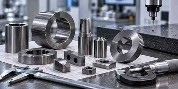
Learn how dimensional tolerances, geometric tolerancing, surface finish, grinding, EDM, lapping, mating dimensions, and functional requirements influence the design and manufacture of precision tungsten carbide components.

Learn how interference, press fits, shrink fits, housing stiffness, thermal expansion, surface condition, mechanical retention, and load distribution influence the design of cemented tungsten carbide-to-steel assemblies.
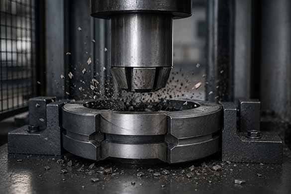
Learn how impact, bending, vibration, cyclic loading, WC grain characteristics, binder systems, geometry, support, and mounting influence carbide grade selection and component design under combined mechanical loads.