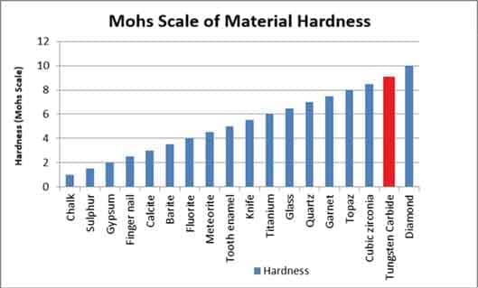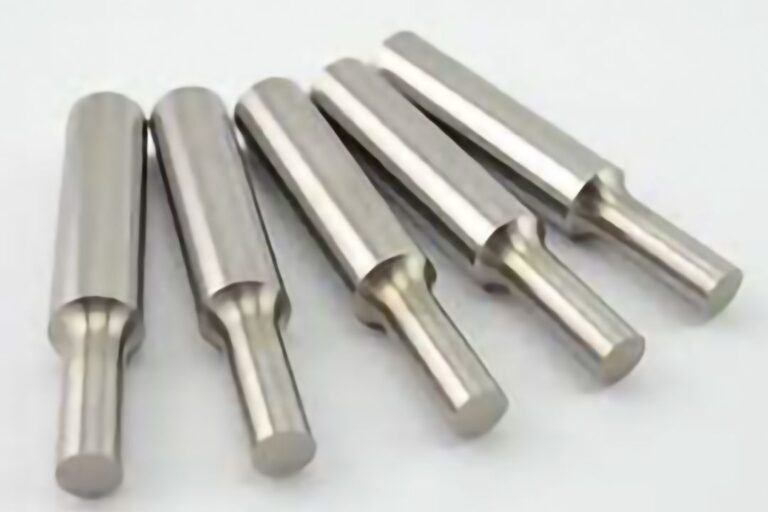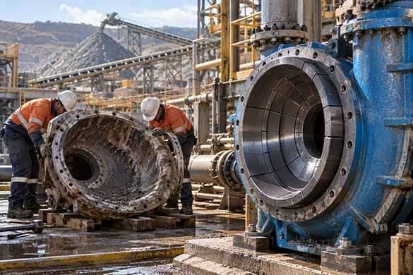
Total Cost of Ownership for Tungsten Carbide Mining Wear Parts
Learn how purchase cost, service life, replacement frequency, maintenance, downtime, and failure risk influence the Total Cost of Ownership of tungsten carbide mining wear parts.

Operating conditions where elevated temperatures, thermal cycling, and mechanical loading interact with wear. Carbide grade, binder system, component geometry, and assembly design must be evaluated according to the actual service temperature and loading conditions.
Tungsten Carbide vs. Steel in Abrasive Applications
Erosion occurs when high-velocity fluids, particles, or particle-laden process streams repeatedly strike component surfaces. It is a critical wear mechanism in flow-control equipment, valves, chokes, nozzles, pumps, separators, and other severe-service process systems.
Tungsten carbide can provide substantially higher erosion resistance than conventional metallic materials when the carbide grade, geometry, flow conditions, and mechanical loading are properly considered.
Choke components and flow restrictors
Valve seats and trim components
Nozzles and orifice inserts
Flow-control wear components
Separator and production-equipment wear parts
Flow velocity
Particle size and concentration
Impact angle
Carbide grade selection
Component geometry
Localized erosion zones
Surface finish and dimensional stability
Valve Seats & Trim · Carbide Nozzles · Flow-Control Inserts
OEM Design Guidelines for Tungsten Carbide
Application-Specific Wear Analysis
Some wear-critical components operate under repeated mechanical loading, impact, vibration, or thermal cycling in addition to abrasive or contact wear.
These conditions are found in mining equipment, steel processing, metal forming, cement production, and other demanding industrial operations.
Because tungsten carbide is extremely hard but can be sensitive to tensile stress and impact depending on grade and geometry, successful application requires the correct balance between wear resistance, toughness, component geometry, and support conditions.
Crusher and mill wear components
Metal-processing wear components
Forming and production tooling
Impact-zone wear inserts
Carbide-to-metal assemblies
Wear resistance versus fracture toughness
Impact and cyclic loading
Stress concentration and component geometry
Thermal expansion differences
Carbide-to-steel joining and support
Application-specific carbide grade selection
Impact Wear Components · Carbide Inserts · Custom Tooling
Tungsten Carbide Wear Solutions for Steel & Metal Processing
Carbide Grade Selection for Mechanically Loaded Components
Many industrial applications experience more than one wear mechanism simultaneously.
Typical combinations include:
Abrasion + erosion
Abrasion + impact
Erosion + corrosion
Pressure + particle erosion
Mechanical loading + elevated temperature
Sliding wear + impact
In these environments, material selection based on hardness alone may not provide the best result. Successful tungsten carbide components require application-specific evaluation of the complete operating environment.
Downhole and surface oil & gas components
Cement and clinker handling
Steel rolling and forming equipment
High-pressure slurry systems
Mineral-processing equipment
Severe-service industrial wear components
Wear-mechanism identification
Carbide grade and binder selection
Component geometry
Stress distribution
Carbide-to-metal interface design
Surface and dimensional requirements
Actual operating conditions
Reverse Engineering Capabilities
Custom OEM Tungsten Carbide Components
Carbide Grades & Material Selection
The same wear mechanism can occur across multiple industries. Industry-specific application notes connect these mechanisms with actual equipment, component geometry, operating conditions, and maintenance requirements.
Typical engineering topics include:
Slurry abrasion
Particle erosion
Impact and abrasive wear
Crusher and grinding-system wear
Hydrocyclone and slurry-system components
Material-handling wear protection
Typical engineering topics include:
Sand and particle erosion
High-velocity flow
Valve and choke wear
Pressure and mechanical loading
Downhole wear conditions
Corrosion-erosion environments
Typical engineering topics include:
Sliding and contact wear
Repeated mechanical loading
Forming and tooling wear
Elevated-temperature operating conditions
Dimensional stability
Continuous-production wear components
Typical engineering topics include:
Abrasive dust and particle wear
Clinker and raw-material handling
Erosion in particle-laden flowhttps://enduracarbide.com/steel-metal-processing-industry.html
Grinding and processing wear
Combined abrasion and impact
Wear-critical material-handling components
• Mining & Mineral Processing • Oil & Gas • Steel & Metal Processing • Cement & Power Generation
Wear performance depends on the actual combination of material, geometry, loading, process media, particle characteristics, temperature, pressure, and operating conditions.
Submit your drawings, specifications, operating conditions, or failed component samples for technical review.
Request Technical Review
Response within 24 hours • NDA available • Technical review included
Slurry transport systems expose wear-critical components to a combination of solid-particle abrasion, particle erosion, fluid-induced loading, and—in some applications—corrosion. These mechanisms rarely act independently. Their interaction can produce complex wear patterns that depend on particle characteristics, slurry velocity and concentration, impact angle, fluid chemistry, component geometry, and operating conditions.
Cemented tungsten carbide combines a hard tungsten carbide (WC) phase with a metallic binder phase, providing a useful balance of hardness, wear resistance, compressive strength, and toughness for demanding slurry applications. However, selecting the hardest available carbide grade does not necessarily provide the longest service life.
Successful material selection requires matching the carbide microstructure, binder system, component geometry, and manufacturing requirements to the dominant wear and loading conditions.
Slurry wear results from repeated interaction between suspended solid particles, the carrier fluid, and exposed component surfaces. The severity and form of wear depend on several interacting parameters.
Particle hardness strongly influences abrasive wear. Hard mineral particles can penetrate, scratch, plow, or micro-cut exposed surfaces when the contact conditions allow them to overcome the surface resistance of the component material.
The very high hardness of the WC phase is one reason cemented tungsten carbide can provide excellent wear resistance in slurries containing hard minerals such as quartz-bearing particles and other abrasive solids.
However, hardness alone does not determine performance. Particle shape, velocity, impact angle, carbide microstructure, binder content, and mechanical loading can substantially change the resulting wear behavior.
Particle size affects both abrasion and impact severity.
Fine particles generally promote repeated micro-abrasion and surface erosion, while larger particles can introduce greater localized impact loads and increase the risk of carbide chipping, cracking, or edge damage.
Consequently, relatively hard carbide grades may perform well in fine-particle abrasive service, whereas applications containing coarse particles or significant impact may require additional toughness.
Actual particle-size distribution—including the presence of occasional oversized particles—should therefore be considered during grade selection.
Increasing solids concentration generally increases the number of particle-surface interactions and can significantly increase wear severity. The relationship is not necessarily linear because particle-particle interaction, slurry rheology, turbulence, and local flow conditions also change as concentration increases.
For this reason, solids concentration should be evaluated together with particle size, velocity, viscosity, and component geometry rather than as an isolated design parameter.
Slurry velocity strongly affects erosion intensity because it influences both particle impact frequency and impact energy.
Wear is often concentrated around:
Therefore, understanding the local flow path can be as important as selecting the carbide grade itself.
Particle impact angle influences the dominant damage mechanism.
Low-angle particle interaction can promote cutting, plowing, and sliding abrasion, while higher-angle impact can increase localized deformation, fracture, and surface damage.
Slurry components exposed to varying particle trajectories may therefore require a carbide grade that balances hardness for abrasion and erosion resistance with sufficient toughness to withstand mechanical impact.
Selecting cemented tungsten carbide for slurry service requires balancing wear resistance, toughness, corrosion behavior, and manufacturing requirements.
WC grain characteristics influence carbide hardness, toughness, and wear behavior.
Finer WC structures generally provide higher hardness and can offer strong resistance to fine-particle abrasion and micro-cutting. Coarser structures can provide greater toughness for applications involving heavier mechanical loading or larger-particle impact.
There is no universally optimum WC grain size. The appropriate structure depends on the actual wear mechanism and operating conditions.
The metallic binder provides cohesion between WC grains and strongly affects carbide toughness.
Lower binder contents are generally associated with higher hardness and wear resistance, while increasing binder content can improve toughness and resistance to fracture. The optimum balance depends on whether the dominant failure mechanism is progressive abrasive wear or impact-related damage.
A useful field diagnostic is the appearance of the failed component:
Failure appearance should not be used as the sole basis for grade selection, but it provides valuable information when combined with operating data and metallurgical analysis.
Corrosive media can change the wear mechanism substantially.
In certain acidic, chloride-containing, or chemically aggressive environments, conventional cobalt-bonded carbide may experience preferential binder attack. Loss of binder support can promote WC grain detachment and accelerate combined corrosion-wear.
Nickel-based or other corrosion-resistant binder systems can be considered when fluid chemistry is a significant design factor.
Binder selection should be based on actual pH, chemical composition, temperature, solids characteristics, and operating conditions rather than on a single pH threshold.
Material selection alone cannot solve every slurry-wear problem. Component geometry and the location of carbide protection can have an equally important influence on service life.
Solid cemented-carbide components can be appropriate for relatively small wear-critical parts such as:
This approach provides carbide protection throughout the component but may become less practical as component size and geometric complexity increase.
For larger or more complex components, localized carbide protection can provide a more practical solution.
Carbide inserts, tiles, liners, or carbide-to-metal assemblies can protect the highest-wear regions while allowing a tougher and more economical metallic structure to carry the primary mechanical loads.
This approach is particularly useful when wear is concentrated in predictable areas rather than distributed uniformly across the entire component.
Wall thickness should provide sufficient structural integrity and usable wear allowance without adding unnecessary carbide volume.
Where wear is highly localized, increasing protection only at critical regions or using replaceable carbide inserts may provide better lifecycle economics than increasing the thickness of the entire component.
Sharp transitions, abrupt flow-path changes, exposed edges, and poorly designed interfaces can concentrate particle impact or mechanical stress.
Geometry should therefore be reviewed together with carbide grade selection.
Surface finish can also be important at precision mating, sealing, and rotating interfaces. Appropriate grinding or polishing can help maintain dimensional control, sealing performance, and predictable fluid behavior.
| Component | Typical Conditions | Material-Selection Direction | Common Wear or Failure Pattern |
|---|---|---|---|
| Hydrocyclone nozzles and underflow components | High-velocity solids-containing slurry | High wear resistance with grade selection based on particle size and impact severity | Orifice enlargement and dimensional wear |
| Slurry-pump wear components | Abrasion, particle erosion and varying impact loads | Balance hardness and toughness according to particle characteristics and component loading | Localized erosion, thinning, grooving or edge damage |
| Pipeline elbows and wear inserts | Concentrated particle impact at changes in flow direction | Localized carbide liners, inserts or replaceable wear protection | Severe outer-radius wear and eventual wall penetration |
| Sleeves and sealing components | Solids-containing fluids and precision mating surfaces | Wear-resistant carbide with appropriate binder system and controlled surface finish | Scratching, dimensional wear and sealing degradation |
| Valve and throttling components | Pressure differential, high local velocity and particle erosion | Application-specific carbide grade, precision geometry and controlled surface finish | Seat/trim erosion, dimensional loss and sealing deterioration |
These are engineering directions rather than universal grade specifications. Final carbide selection should be based on the actual service environment.
There is no single cemented-carbide grade that is optimum for every abrasive slurry application. A more reliable selection process considers the entire wear system.
Determine whether the component is primarily experiencing:
Correctly identifying the dominant mechanism is the foundation of material selection.
Collect relevant application data, including:
These parameters provide the engineering basis for carbide-grade and component-design decisions.
Balance:
The objective is not simply maximum hardness. It is the combination of properties most appropriate for the dominant failure mechanism.
Determine whether the application is best served by:
Protecting the correct region can be more effective and economical than increasing carbide usage throughout the component.
Laboratory wear testing is useful for comparing materials, but it cannot reproduce every combination of particle characteristics, hydrodynamics, mechanical loading, corrosion, geometry, and operating variation encountered in industrial equipment.
Where practical, candidate grades and component designs should therefore be validated through controlled field trials before full-scale implementation.
Cemented tungsten carbide normally has a higher initial material and manufacturing cost than conventional steel. The engineering comparison should therefore consider total lifecycle performance rather than purchase price alone.
Relevant factors include:
In severe abrasive and erosive environments, extending service intervals or protecting only the highest-wear regions can justify a higher initial component cost.
However, lifecycle improvement should be evaluated using actual application data rather than assuming a fixed service-life multiplier for tungsten carbide.
Abrasive slurry wear is a system-level engineering problem involving particles, fluid flow, mechanical loading, corrosion, component geometry, and material properties.
Cemented tungsten carbide can provide exceptional performance in these environments, but successful application depends on selecting the appropriate combination of WC grain characteristics, binder system, hardness, toughness, corrosion resistance, component geometry, and wear-protection strategy.
The most effective solution is therefore not necessarily the hardest carbide grade. It is the grade and component design that best match the dominant wear mechanisms and actual operating conditions.
For critical slurry applications, field performance data should be used to validate and refine material selection over time.
Particle erosion is a major wear mechanism in industrial fluid-handling and flow-control systems. Unlike general sliding abrasion, particle erosion involves progressive material loss caused by repeated impact of solid particles entrained in a moving fluid.
In high-velocity flow systems used in oil and gas, chemical processing, power generation, mineral processing, and other severe-service industries, localized particle erosion can alter critical dimensions, reduce sealing or flow-control performance, and shorten component service life.
Cemented tungsten carbide combines hard tungsten carbide (WC) grains with a metallic binder phase. This composite microstructure provides a useful combination of hardness, erosion resistance, compressive strength, and toughness. However, not all carbide grades perform equally under erosive conditions.
Successful material selection requires understanding particle characteristics, velocity, impact angle, fluid chemistry, mechanical loading, component geometry, and the location of concentrated erosion.
Particle erosion occurs when solid particles carried by a gas or liquid repeatedly strike a component surface and remove material through mechanisms such as micro-cutting, plowing, localized deformation, micro-fracture, and progressive material detachment.
The resulting erosion rate cannot be predicted from one parameter alone. It depends on the interaction between the particles, fluid, component material, geometry, and operating conditions.
Velocity is one of the most influential parameters in particle erosion.
As particle velocity increases, both impact frequency and impact energy can increase, potentially accelerating material removal substantially. However, the relationship between velocity and erosion rate varies with particle properties, target material, flow regime, geometry, and other operating conditions.
This makes velocity particularly important in components such as:
Rather than relying on a universal velocity threshold, erosion risk should be evaluated using the actual flow conditions and component geometry.
Increasing solids concentration generally increases the number of particle-surface interactions and can increase erosion severity.
However, the relationship is not necessarily linear. At higher particle concentrations, particle-particle interactions, fluid behavior, turbulence, and particle trajectories can change.
Particle concentration should therefore be evaluated together with velocity, particle size and shape, fluid properties, and local flow geometry.
Particle size influences particle inertia and impact behavior.
Larger particles generally carry greater impact energy and may be more likely to deviate from fluid streamlines and strike exposed surfaces. Fine particles may follow the flow more closely, although they can still cause significant erosion where local velocity, turbulence, concentration, or geometry promotes repeated surface interaction.
Particle shape also matters. Angular or sharp-edged particles can promote cutting and plowing, while more rounded particles may produce a different balance of deformation and impact-related damage.
For carbide selection, particle-size distribution and shape should therefore be considered together with impact angle and mechanical loading.
The angle at which particles strike a surface strongly influences the resulting damage mechanism.
At relatively low impact angles, particles can slide or move across the surface, promoting:
At higher impact angles, the damage mechanism can shift toward:
For cemented tungsten carbide, this distinction is important because high hardness supports resistance to cutting and abrasion, while sufficient toughness is needed where impact-related fracture becomes significant.
The optimum grade therefore depends on the actual distribution of particle trajectories rather than on hardness alone.
Industrial flow systems rarely experience perfectly uniform flow.
Changes in direction, restrictions, abrupt transitions, exposed edges, ports, and other geometric features can alter particle trajectories and create localized erosion zones.
Common examples include:
These effects make flow-path geometry a critical part of erosion-resistant component design. Material selection alone may not compensate for unfavorable geometry.
In valves, chokes, nozzles, and other flow-control components, pressure differential can contribute to high local fluid and particle velocities.
The resulting erosion severity depends on the pressure conditions together with fluid properties, solids loading, particle characteristics, geometry, and flow regime.
For this reason, components operating across substantial pressure differentials often require careful evaluation of both material selection and flow-path design.
Selecting cemented tungsten carbide for particle-erosion service requires balancing hardness, toughness, binder characteristics, corrosion resistance, and manufacturing requirements.
WC grain characteristics influence carbide hardness, toughness, and resistance to different erosion mechanisms.
Finer WC structures generally provide higher hardness and can offer strong resistance to micro-cutting and fine-particle erosion.
Where larger particles, higher-angle impact, vibration, or mechanical loading increase the risk of cracking or edge damage, a carbide structure providing greater toughness may be preferable.
There is no universally optimum WC grain size for particle erosion. Grade selection should be based on the actual erosion and loading conditions.
The metallic binder provides cohesion between WC grains and strongly influences carbide toughness.
Lower binder contents are generally associated with higher hardness and wear resistance, while increasing binder content can provide greater toughness and resistance to fracture.
This creates an important engineering tradeoff:
Fixed binder percentages should not be selected from erosion type alone. Component geometry, particle characteristics, mechanical loading, manufacturing requirements, and actual field performance should also be considered.
Fluid chemistry can significantly influence carbide performance.
In certain corrosive environments, conventional cobalt-bonded tungsten carbide may experience preferential attack of the binder phase. This can weaken support around WC grains and accelerate combined erosion-corrosion damage.
Nickel-based or other corrosion-resistant binder systems can be considered when fluid chemistry is a significant design factor.
The appropriate binder system should be selected according to actual fluid composition, pH, temperature, pressure, solids characteristics, and other operating conditions.
Surface finish can be important in precision flow-control and sealing components.
Surface irregularities may influence local fluid behavior, particle interaction, sealing performance, and the initiation of localized damage. Appropriate grinding, lapping, or polishing can therefore be beneficial where dimensional accuracy and controlled surface condition are important.
Examples include:
The required surface finish should be specified according to the functional requirements and actual operating conditions rather than applying one universal roughness value to all erosion applications.
Particle erosion is frequently localized rather than uniformly distributed across a component.
Typical erosion-prone regions include:
Understanding where erosion actually occurs allows engineers to determine whether an entire component needs to be manufactured from carbide or whether localized carbide protection is more appropriate.
For larger or more complex components, carbide can be concentrated at the regions experiencing the most severe wear through:
This approach allows a tougher metallic structure to carry the primary mechanical loads while carbide protects the critical erosion zones.
In many applications, targeted protection can provide a more practical balance between wear performance, structural reliability, manufacturability, and lifecycle cost than manufacturing the entire component from solid carbide.
For components exposed to particle erosion in high-velocity flow, consider the following engineering principles.
Identify restrictions, pressure drops, accelerated-flow regions, and other locations where particle velocity may increase significantly.
Where system requirements allow, reducing unnecessary local acceleration can help reduce erosion severity.
Gradual transitions and appropriately designed flow paths can help reduce abrupt changes in particle trajectories and localized turbulence.
Particular attention should be given to:
In some flow-control applications, distributing pressure reduction across multiple stages can help manage local velocity and erosion.
Whether this approach is suitable depends on system requirements, fluid properties, solids characteristics, and equipment design.
Where erosion is concentrated in predictable regions, replaceable carbide inserts, sleeves, or other wear elements can simplify maintenance and reduce the need to replace larger assemblies.
Consider:
Do not select a grade based on hardness alone.
Where corrosive species or aggressive process fluids are present, evaluate whether the binder system provides suitable corrosion resistance in addition to erosion resistance.
| Component | Typical Erosion Challenge | Material-Selection Direction |
|---|---|---|
| Valve seats and trim | High local velocity, particle erosion and pressure differential | Balance erosion resistance, toughness, dimensional stability and surface-finish requirements |
| Choke components | Severe localized erosion around restrictions and flow transitions | Application-specific carbide grade with attention to particle characteristics, impact conditions and geometry |
| Nozzles | High-velocity particle-laden flow and progressive dimensional wear | High wear resistance with grade selection based on particle characteristics and impact severity |
| Orifices and flow-control inserts | Concentrated erosion around bore edges and downstream regions | Wear-resistant carbide with precision geometry and controlled surface finish |
| Elbows and bends | Concentrated particle impact caused by changes in flow direction | Localized carbide inserts, liners or other targeted wear protection where appropriate |
| Sleeves and bushings | Particle ingress, dimensional wear and possible mechanical loading | Balance wear resistance, toughness, dimensional stability and surface requirements |
These are engineering directions rather than universal carbide-grade specifications. Final grade selection should be based on actual operating conditions.
A reliable particle-erosion solution should consider the complete operating system rather than treating carbide grade as an isolated variable.
Determine whether material loss is primarily associated with:
Collect relevant information including:
Evaluate the required combination of:
Determine whether the application requires:
Laboratory testing can help compare candidate materials, but actual industrial erosion depends on the complete combination of flow conditions, particle characteristics, geometry, mechanical loading, and fluid chemistry.
For critical applications, candidate grades and component designs should therefore be validated under representative or actual service conditions where practical.
Particle erosion in high-velocity flow is a system-level engineering problem.
Velocity, particle concentration, particle size and shape, impact angle, fluid chemistry, pressure conditions, mechanical loading, and flow-path geometry can all influence the dominant damage mechanism.
Cemented tungsten carbide provides engineers with several variables that can be adjusted for these conditions, including WC grain characteristics, binder content, binder type, component geometry, and surface finish.
The most effective solution is therefore not necessarily the hardest carbide grade.
It is the combination of carbide properties and component design that best matches the actual erosion mechanism, localized wear pattern, and operating environment.
By identifying where and how erosion occurs—and validating the selected material under representative service conditions—engineers can develop more reliable and cost-effective wear solutions for demanding high-velocity flow applications.
Cemented tungsten carbide components operating under impact and combined mechanical loads present a different engineering challenge from components exposed mainly to progressive abrasion or particle erosion.
Under abrasive wear, material loss may develop gradually. Under impact, bending, vibration, or cyclic mechanical loading, damage can instead involve edge chipping, crack initiation, spalling, fatigue-related damage, or sudden fracture.
Cemented tungsten carbide provides very high hardness, compressive strength, and wear resistance, but these properties alone do not determine performance under impact conditions.
The engineering objective is therefore not simply to specify the hardest available carbide grade or to describe a material as universally “impact resistant.” Successful design requires an appropriate balance of:
Cemented tungsten carbide performs particularly well when loads are predominantly compressive. However, impact, bending, edge loading, or inadequate support can introduce tensile and shear stresses that are less favorable for a hard, relatively brittle material.
For this reason, a carbide component that performs extremely well under abrasion may not necessarily provide the best performance when exposed to repeated impact or bending.
A single severe overload can initiate cracking or fracture, while repeated lower-level loads may progressively accumulate damage.
The relevant design question is therefore not simply:
How hard is the carbide?
It is:
What combination of hardness, toughness, geometry, support, and load distribution is appropriate for the actual failure mechanism?
Pure impact without accompanying wear is relatively uncommon in many industrial applications.
More often, impact interacts with abrasion, particle erosion, vibration, compression, or other mechanical loads.
Typical combined conditions include:
Identifying which mechanism dominates is essential.
When progressive wear controls service life, greater hardness and wear resistance may be advantageous. When fracture or chipping dominates, greater toughness, improved geometry, and better support may become more important.
Repeated mechanical loading can gradually initiate and propagate damage even when individual load events are insufficient to cause immediate fracture.
Potential initiation sites include:
Vibration can introduce repeated small-amplitude loading and, at contacting interfaces, may also contribute to fretting or localized surface damage.
The significance of these effects depends on load magnitude, frequency, contact conditions, support stiffness, geometry, surface condition, and material properties.
Bending is particularly important because it produces a non-uniform stress state rather than purely compressive loading.
If a carbide component is inadequately supported, an impact force that appears compressive at the system level can generate localized bending or tensile stresses within the carbide.
Edge loading can create a similar problem. When force is concentrated near an unsupported edge, the effective load-bearing area decreases and local stresses can increase substantially.
Stress concentration can also arise from:
For impact-loaded carbide components, minimizing these stress raisers is often as important as selecting the carbide grade itself.
Toughness in cemented tungsten carbide is influenced by several interacting microstructural variables rather than by a single property.
WC grain characteristics influence the balance between hardness, wear resistance, and fracture behavior.
Finer WC structures generally provide greater hardness and can offer strong resistance to abrasion and micro-cutting.
Where impact, bending, larger particles, intermittent contact, or other mechanical loads increase the risk of cracking or chipping, a carbide structure providing greater toughness may be preferable.
There is no universally optimal WC grain size for impact-loaded components.
The required grain characteristics should be selected together with binder content, component geometry, wear severity, support conditions, and actual loading.
The metallic binder contributes significantly to the toughness and fracture behavior of cemented tungsten carbide.
In general:
This means grade selection should be based on the dominant failure mode rather than on one fixed binder percentage.
If a component is wearing away without cracking, greater wear resistance may be needed.
If it is chipping, cracking, or fracturing before substantial wear occurs, a different hardness-toughness balance—or changes to geometry and support—may be required.
Binder composition can also influence performance when corrosion is present together with mechanical loading.
Conventional cobalt-bonded carbide provides excellent performance in many applications, but the binder phase may be vulnerable to preferential attack in certain aggressive chemical environments.
Nickel-based or other corrosion-resistant binder systems can be considered when fluid chemistry is an important part of the failure mechanism.
However, binder selection should not be based on corrosion resistance alone.
The actual combination of:
should be considered before selecting the binder system.
Selecting an appropriate carbide grade is only part of successful impact-loaded component design.
Geometry and support conditions can determine whether the carbide experiences favorable compressive loading or unfavorable bending, tensile stress, or concentrated edge loading.
The cross-section should provide sufficient stiffness and load-bearing area while avoiding unnecessary geometric discontinuities.
Very thin sections may be vulnerable to:
However, simply increasing carbide thickness does not automatically solve the problem.
Large or complex carbide sections can introduce additional manufacturing, sintering, dimensional-control, thermal, assembly, and cost considerations.
Wall thickness should therefore be selected according to:
Gradual section transitions are generally preferable to abrupt changes where impact or bending stresses are significant.
Support is one of the most important external factors in the performance of impact-loaded carbide components.
A well-supported carbide element can transfer a greater proportion of the applied load through compression and reduce bending.
By contrast, gaps, uneven contact, unsupported regions, or excessive overhang can create localized stresses and increase the risk of fracture.
For many applications, a carbide-to-steel assembly provides an effective design strategy:
This allows each material to perform the function for which it is best suited.
The carbide should be supported consistently across the intended load-bearing surfaces.
Poor contact between carbide and its supporting structure can allow localized movement or bending under impact.
Important considerations include:
The appropriate fit should be determined from the actual assembly design rather than by applying one fixing method universally.
Several methods can be used to integrate cemented tungsten carbide into a larger assembly.
Each has advantages and limitations.
| Retention Method | Potential Advantages | Engineering Considerations |
|---|---|---|
| Brazing | Strong permanent attachment and good load transfer when correctly designed | Thermal cycles, residual stress, joint design, filler selection, and service temperature must be controlled |
| Interference or press fit | No brazing heat; can provide strong mechanical support | Requires careful tolerance, stress analysis, assembly control, and allowance for thermal expansion |
| Mechanical clamping | Replaceable carbide element and easier maintenance | Clamp-force distribution, movement, contact pressure, and localized stress must be controlled |
| Bonded or engineered composite assembly | Can distribute load over a relatively large interface | Adhesive or bonding system must suit temperature, chemistry, load, and service environment |
| Other engineered retention methods | Can be adapted to specialized geometries | Must be validated for actual mechanical, thermal, and environmental conditions |
There is no single preferred mounting method for all impact applications.
The correct solution depends on component geometry, temperature, required replaceability, impact severity, load direction, tolerances, manufacturing capability, and operating environment.
Regardless of the retention method, concentrated point loading on the carbide should generally be avoided where it creates an unfavorable stress concentration.
Broad, controlled support surfaces are usually preferable.
Impact-loaded carbide components generally benefit from geometry that minimizes local stress concentration.
Important principles include:
There is no universal minimum corner radius suitable for every carbide component. The appropriate radius must be established from the geometry, component size, load case, and functional requirements.
Failed carbide components can provide valuable information about whether the original design correctly matched the operating conditions.
However, the cause of failure should not be inferred from fracture appearance alone.
A reliable failure investigation should consider:
Certain observations can help guide investigation:
These observations are diagnostic indicators rather than definitive failure classifications.
A fracture surface alone should not be used to assign a root cause without considering the full service history and component design.
Determine whether existing or comparable components primarily fail through:
Collect available information on:
Exact impact energy may not always be available. In such cases, field observations, equipment operating data, damage patterns, and comparison with previous components can still support material selection.
Evaluate:
Choose an initial grade based on the required balance of:
Avoid assuming that either the maximum-hardness grade or maximum-toughness grade is automatically the best starting point.
Review:
In many cases, geometry or support modifications can be as important as changing the carbide grade.
Laboratory testing can help compare materials and designs, but actual field conditions may combine impact, vibration, abrasive particles, temperature, corrosion, and irregular loading.
For critical components, candidate grades and geometries should therefore be validated under representative or actual operating conditions where practical.
Record:
Use these results to refine the carbide grade, geometry, support, or retention method during subsequent design iterations.
Selecting cemented tungsten carbide for impact and combined mechanical loading is not simply a matter of choosing the hardest grade.
Reliable performance depends on the interaction of several factors:
The objective should not be to claim a universally “impact-resistant” carbide grade.
Instead, the goal is to engineer a component system in which the carbide grade, geometry, support structure, interfaces, and load conditions work together.
When these factors are matched to the actual failure mechanism, cemented tungsten carbide can provide both high wear resistance and reliable service in demanding applications involving impact and combined mechanical loads.
The purchase price of a mining wear component represents only one part of its true operating cost. Replacement frequency, installation labor, planned and unplanned downtime, service life, and the consequences of premature failure can significantly affect lifecycle economics. This article presents a practical Total Cost of Ownership (TCO) framework for evaluating tungsten carbide wear components and explains how material selection, operating conditions, wear mechanisms, and maintenance requirements influence cost per operating hour.
Procurement decisions for mining wear components are often influenced by initial purchase price. However, comparing components solely on unit price can overlook significant lifecycle costs associated with installation, replacement frequency, maintenance labor, downtime, and premature failure.
A higher-priced wear component may provide a lower cost per operating hour when longer service life reduces replacement frequency, maintenance requirements, and wear-related downtime. Conversely, tungsten carbide is not automatically the most economical solution for every application. Its value depends on the dominant wear mechanism, impact loading, component design, service life, replacement requirements, and the operational consequences of downtime.
Total Cost of Ownership provides a structured way to evaluate these factors using actual application data rather than purchase price alone.
A practical starting point for comparing mining wear components is:
Cost per Operating Hour = Total Lifecycle Cost ÷ Total Operating Hours
Total lifecycle cost may include component costs, installation labor, associated maintenance costs, and the economic impact of planned or unplanned downtime over the evaluation period.
This approach converts different wear-component options into a common operating-cost basis. The calculation should use actual site data wherever possible because service life, replacement frequency, labor requirements, and downtime costs can vary significantly between applications and operating environments.
For material-processing equipment, another useful production-based metric is:
Lifecycle Cost per Tonne Processed = Total Lifecycle Cost ÷ Total Tonnes Processed
The most appropriate metric depends on the equipment and operation. Operating hours may be suitable for some components, while tonnes processed, cycles, drilling distance, or another measurable production parameter may provide a more meaningful comparison in other applications.
Downtime can represent a significant portion of the lifecycle cost of a wear component, particularly when replacement interrupts a critical production process.
Planned replacement during a scheduled maintenance window may have relatively predictable labor and production effects. Unexpected failure, however, can create additional costs through emergency maintenance, production interruption, secondary component damage, and disruption to downstream or upstream operations.
For this reason, TCO calculations should distinguish between planned replacement costs and the potentially greater consequences of unplanned failure.
This creates an important lifecycle relationship:
Shorter service life → More replacement events → More maintenance interventions → Greater downtime exposure
Conversely, longer and more predictable service intervals can reduce the number of wear-related interventions over the evaluation period.
Service life should be measured using an operating metric appropriate to the application, such as operating hours, tonnes processed, drilling distance, cycles, or another measurable production parameter.
The relative service life of tungsten carbide and conventional wear materials can vary considerably with abrasive characteristics, impact loading, slurry conditions, component geometry, carbide grade, attachment method, and equipment operating parameters.
Longer service life can improve TCO by reducing replacement frequency, but service life should not be evaluated independently of failure mode. A component that wears gradually and predictably may provide greater operational value than one that offers high wear resistance but is vulnerable to sudden fracture under inappropriate loading conditions.
Purchase price remains an important part of TCO, but it should be evaluated relative to expected service life rather than considered independently. Custom geometry, carbide grade, tolerances, component size, finishing requirements, and attachment design can all influence initial component cost.
Each replacement may involve disassembly, installation, alignment, inspection, labor, tooling, and recommissioning. Components requiring frequent replacement can therefore accumulate significant maintenance costs even when their individual purchase price is relatively low.
The economic effect of downtime depends on where the component is installed. Failure of a wear component in a production-critical system may have a substantially greater consequence than replacement of an accessible component during scheduled maintenance.
Longer service intervals can reduce replacement frequency, but predictable wear behavior is also important. A component that wears gradually and consistently can often be inspected and replaced during a scheduled maintenance window rather than after an unexpected failure.
Predictable service life can support better shutdown planning, spare-parts planning, labor allocation, and replacement scheduling. Components should therefore be inspected and replaced before dimensional loss or damage affects equipment performance, surrounding components, or contributes to an unplanned shutdown.
For critical mining equipment, the operational value of predictable wear can sometimes be as important as the increase in service life itself.
TCO calculations should account for the possibility of fracture, chipping, pull-out, loosening, corrosion-assisted degradation, or other premature failure mechanisms. Carbide grade, component geometry, support conditions, attachment method, and manufacturing consistency can all influence this risk.
Consider two hypothetical wear-component options operating under the same conditions:
| Cost Factor | Conventional Component | Carbide Component |
|---|---|---|
| Component cost | Enter actual cost | Enter actual cost |
| Service life | Enter actual operating hours | Enter actual operating hours |
| Number of replacements | Calculate | Calculate |
| Installation cost | Enter actual cost | Enter actual cost |
| Downtime per replacement | Enter actual time | Enter actual time |
| Downtime cost | Calculate using site data | Calculate using site data |
| Total lifecycle cost | Calculate | Calculate |
| Cost per operating hour | Total lifecycle cost ÷ total operating hours | Total lifecycle cost ÷ total operating hours |
The purpose of this comparison is not to assume that carbide will always produce the lower TCO. Instead, it provides a consistent framework for determining whether higher initial component cost can be offset by longer service life, fewer replacement events, and reduced wear-related downtime.
Tungsten carbide may provide a lifecycle-cost advantage where:
Conversely, tungsten carbide may not provide the strongest economic case in low-wear locations, where components are inexpensive and easy to replace, or where operating conditions cannot be adequately addressed through carbide grade, geometry, support, and attachment design.
The purpose of TCO analysis is therefore not to demonstrate that tungsten carbide is always the preferred material, but to identify the applications in which its performance characteristics can create measurable lifecycle value.
Carbide selection should still account for impact, vibration, bending, thermal conditions, corrosion, support geometry, and attachment method. In applications dominated by severe impact or structural deformation, simply increasing hardness may not provide the lowest TCO.
Tungsten carbide may provide a TCO advantage in applications dominated by abrasion and particle erosion, where hard particles continuously slide, grind, or impinge against component surfaces. These wear mechanisms can progressively remove material, alter critical dimensions, and increase replacement frequency.
The high hardness and wear resistance of cemented tungsten carbide can help reduce material loss in suitable applications. Where this results in longer service intervals, the higher initial component cost may be offset by fewer replacements, reduced maintenance requirements, and lower wear-related downtime.
The TCO advantage of tungsten carbide can become more significant when maintenance and replacement requirements are high. Each replacement may involve not only the cost of the component itself but also installation labor, downtime, production impact, and logistical requirements.
If a carbide component provides a longer service interval under the actual operating conditions, the number of replacement events over the evaluation period may decrease. This can reduce cumulative installation costs, wear-related downtime, and maintenance requirements. In suitable applications, these savings can help offset the higher initial cost of the carbide component and reduce cost per operating hour.
Tungsten carbide provides high hardness and wear resistance, but applications involving substantial impact or cyclic mechanical loading require careful consideration of toughness and structural support.
WC grain characteristics, binder content, component geometry, support conditions, and attachment method influence the balance between wear resistance and fracture risk. The hardest available carbide grade is therefore not necessarily the grade that provides the lowest lifecycle cost.
TCO analysis should consider both progressive wear and the potential consequences of premature fracture or component loss.
Because material and manufacturing costs can change over time, TCO comparisons should use current quotations and actual operating data rather than historical price assumptions. Site-specific labor, maintenance, downtime, and service-life data provide a more reliable basis for comparing alternative wear-component solutions.
Improving the service life of one wear component does not necessarily extend the maintenance interval of the entire equipment system.
When a rapidly wearing component is upgraded with tungsten carbide, the wear bottleneck may shift to adjacent liners, guides, supports, sleeves, bushings, nozzles, fasteners, or downstream components.
TCO evaluation should therefore consider whether surrounding components can support the longer operating interval. If another component still requires an earlier shutdown, part of the economic benefit expected from the carbide upgrade may not be realized.
A system-level assessment can include:
The objective is not simply to maximize the life of one carbide component, but to improve the reliability and lifecycle economics of the overall wear system.
The purchase price of a mining wear component is only one part of its economic impact. Service life, replacement frequency, installation labor, downtime, maintenance requirements, and the consequences of premature failure can significantly influence the true cost per operating hour.
Tungsten carbide can provide lifecycle-cost advantages in applications dominated by abrasion, particle erosion, and dimensional wear, particularly where component replacement is difficult or downtime is costly. However, the lowest TCO does not automatically come from the hardest material or the component with the longest theoretical wear life.
The most useful TCO analysis combines actual operating data with an application-specific evaluation of wear mechanisms, carbide grade, component geometry, support conditions, and replacement requirements. This allows engineers and procurement teams to compare wear-component options based on lifecycle performance rather than unit purchase price alone.
Learn how purchase cost, service life, replacement frequency, maintenance, downtime, and failure risk influence the Total Cost of Ownership of tungsten carbide mining wear parts.
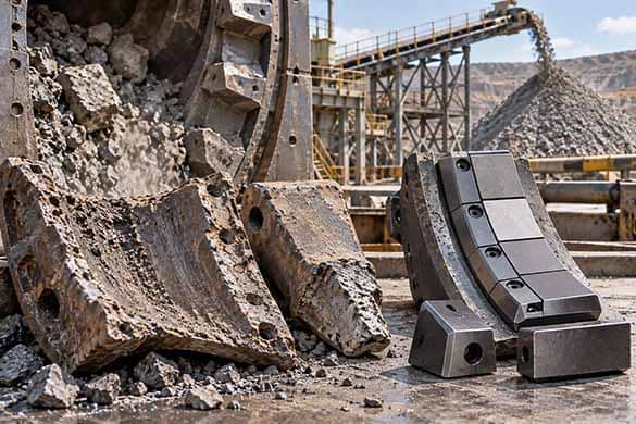
Learn why mining wear components fail under abrasion, particle erosion, impact, fatigue, corrosion-assisted wear, and mechanical loading, and how carbide grade and component design can be matched to demanding operating conditions.
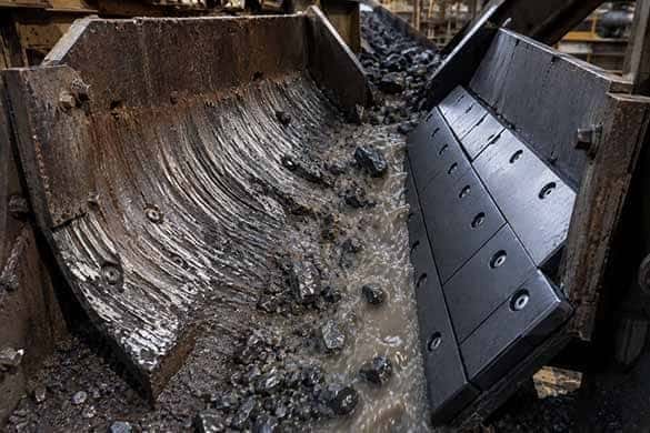
Mining wear parts can fail through abrasion, particle erosion, impact, corrosion, fracture, poor material selection, or manufacturing and design defects. This article explains how tungsten carbide can address these failure mechanisms through application-specific hardness, toughness, binder selection, microstructural control, and component design.
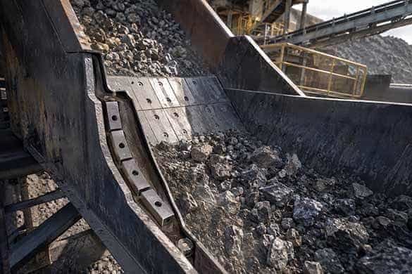
Tungsten carbide can extend the service life of mining wear components by combining high wear resistance with application-specific toughness, binder selection, microstructural control, and component design. This article explains how these factors help resist abrasion, impact, slurry erosion, corrosion, and other severe mining wear conditions.
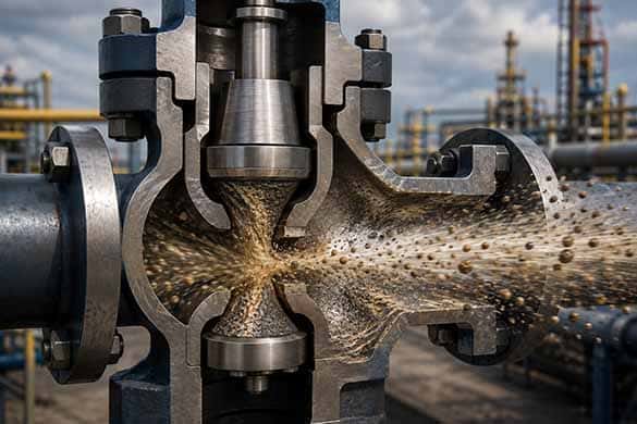
Particle erosion, abrasion, cavitation, corrosion, and mechanical loading can rapidly damage oil and gas flow-control components. This article explains how particle characteristics, flow velocity, impact angle, geometry, binder system, WC grain structure, and component design influence failure—and how tungsten carbide can be engineered for severe-service applications.
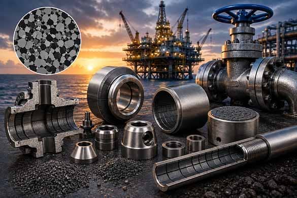
Tungsten carbide performs in severe oil and gas service through more than hardness alone. WC grain structure, binder chemistry, microstructural control, component geometry, manufacturing quality, and coating technologies all influence resistance to abrasion, particle erosion, corrosion, impact, and mechanical loading.

Vertical roller mills expose wear-critical components to severe abrasion, particle erosion, high contact pressures, and mechanical loading. Learn how application-specific tungsten carbide wear studs, inserts, plates, and other engineered components can help extend replacement intervals and reduce wear-related maintenance in demanding VRM applications.
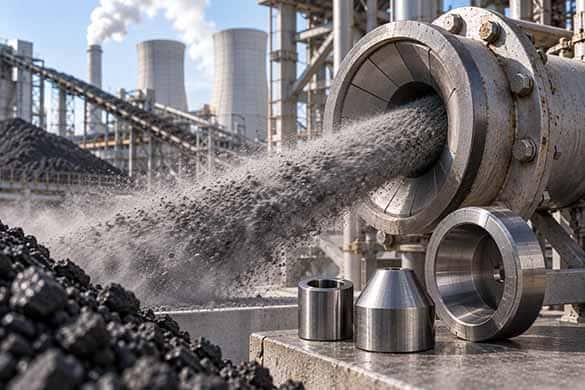
Coal, fly ash, and entrained mineral particles can cause severe abrasion and high-velocity erosion in power-generation applications. Learn where tungsten carbide nozzles, liners, sleeves, and other flow-path components can help maintain critical geometry and extend replacement intervals.
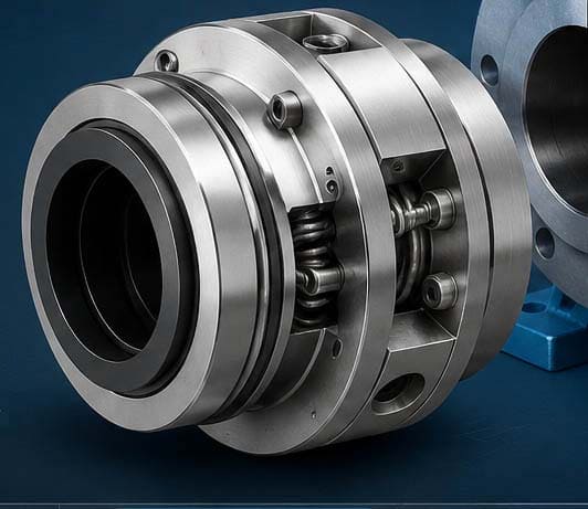
Cartridge mechanical seals reduce leakage, simplify installation, and protect critical pump components. Tungsten carbide seal faces further improve wear resistance in abrasive and demanding operating conditions.
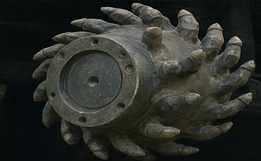
Precision, speed, and material efficiency are the hallmarks of modern furniture and cabinetry production. As design trends move toward tighter tolerances, thinner materials, and more complex geometries, the performance of cutting tools within production equipment becomes a critical differentiator. F